Introduction
We are happy to welcome you to the Frolight family and thank you for choosing
our product.
Frolight is a revolutionary solution designed to protect your vineyard from
damage caused by spring frost. Our advanced infrared lighting technology
works to raise the temperature of the vineyards and provide optimal growing
conditions for your plants. This innovative system allows you to increase your
yields and maintain the quality of your grapes, ensuring that your vineyard can
produce the best wines possible.
Whether you are a professional vineyard manager, or a hobbyist who takes
care of your own grapes, Frolight is an easy-to-use, reliable solution that can
provide you with the protection you need to keep your vineyard in top
condition. The manual is designed to guide you through the setup, operation,
and maintenance of your Frolight system, so that you can start seeing the
benefits of healthier, more productive vines as soon as possible.
We hope that you will find the user manual informative and easy to understand.
Enjoy your Frolight!
General safety warnings & precautions
Please read this manual carefully.
Contact your point of sales if you have any questions.

This product is intended for professional use only. It should not be operated by untrained individuals or children
under the age of 12. To prevent the risk of electrocution and injury, children should always be kept at a safe distance from the system.

This product is designed for outdoor use only. Using this device indoors or in enclosed spaces can lead to serious damage, injury, or fire.

This product uses electrical power and three-phase voltage Always turn off and disconnect the Control Unit from the power
source before installing or uninstalling. Always turn off and disconnect the Control Unit from the power source before connecting any IR tubes or extension cables.
Do not dismantle the Control Unit or IR tubes.
Make sure that the power supply voltage has been correctly measured by an electrician before connecting the control unit.
If a generator is used, make sure that the grounding has been properly installed and connected.
Safely handle IR tubes: .
Failure to adhere to any of these guidelines could result in death or serious injury and may also void the warranty
Product Overview
The Frolight system protects your vineyard from spring frost damage by radiating infrared light onto the root stocks of the vine plants. This infrared light comes from IR tubes. These IR tubes are installed close to the root stocks. The IR tubes are connected to and controlled by the Control Units (FLGCU-A & FLGCU-B), which act as the brain of the system. The Master Control Unit is required for every Frolight installation. Additional Slave Control Units can be added to protect a larger area on your location. Configuration and monitoring is done via the Master Control Unit. The Master Control Unit communicates with the Slave Control Units wirelessly over radio signals. Below is a schematic overview of a Frolight setup with 1 Master Control Unit and 2 Slave Control Units protecting 36 rows.
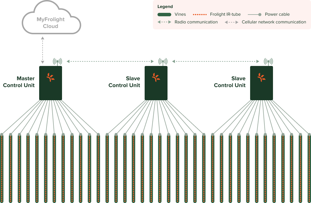
Only one Master per location allowed
The Frolight system is intended to be used on a single location. Do not install multiple Master Control Units on the same location. Always use Slave Control Units to extend a system’s reach. However, if you have multiple locations to protect, you should set up a Frolight installation with at least a Master Control Unit per location.
Parts
A minimal Frolight setup includes the following components:

Master Control Unit (FLGCU-A)
The brain of the system, this smart electrical unit connects to the IR tubes.
The master control unit is mounted onto a metal base.
This unit also handles the connection with the MyFrolight web platform.
Discover more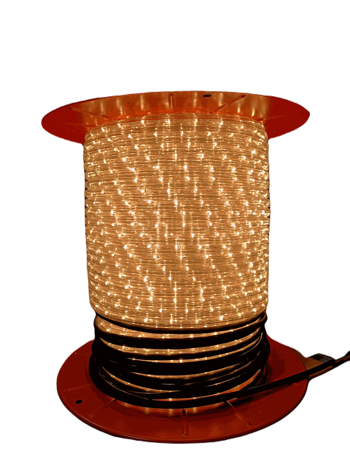
IR tubes (FLH-MXXX)
These infrared light tubes are the workhorses of the Frolight system.
IR tubes come on a reel that can be unrolled in the vineyard. They come in varying lengths, from 25 to 150 metres.

Slave Control Unit (FLGCU-B)
If the vineyard’s area that must be protected is too large for a single control unit, one slave control unit must be added per extra 1200 meters of IR tube.
The slave control unit is very similar to the master control unit. However, it receives it’s settings from the master control unit and it does not contain a USB dongle with a SIM card. MyFrolight connectivity is handled by the master control unit.
Master and slave control units can be visually distinguished by respectively a green (master) and blue (slave) indicator label.
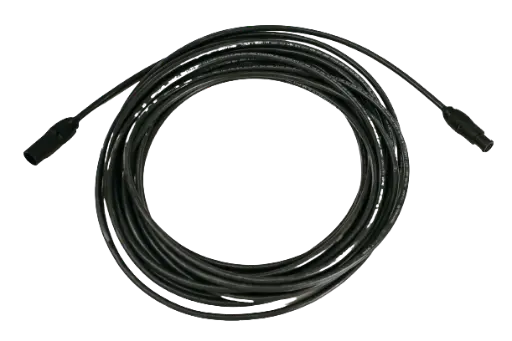
Extension Cable (FLACTB-MXXX)
An IR tube has 10 meters of power cable to reach the control unit. If this is not sufficient, an extension cable can be used to extend the length with an extra 5 to 100 meters
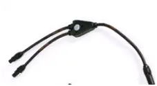
Power Cable Splitter (FLACTB-SP01)
If you
need to connect more than 12 IR tubes to a control unit, a splitter can be
used to turn one connection into two new connections.
Please be
aware that use of this option is limited and to not connect more than 1200
meters per control unit.
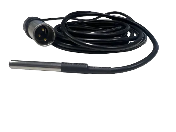
Extra Sensor (FLACTS2-M01)
A second Temperature Sensor can be added to measure and keep track of the temperature at two different locations. This can come with an additional cable of between 1 to 100 meters.
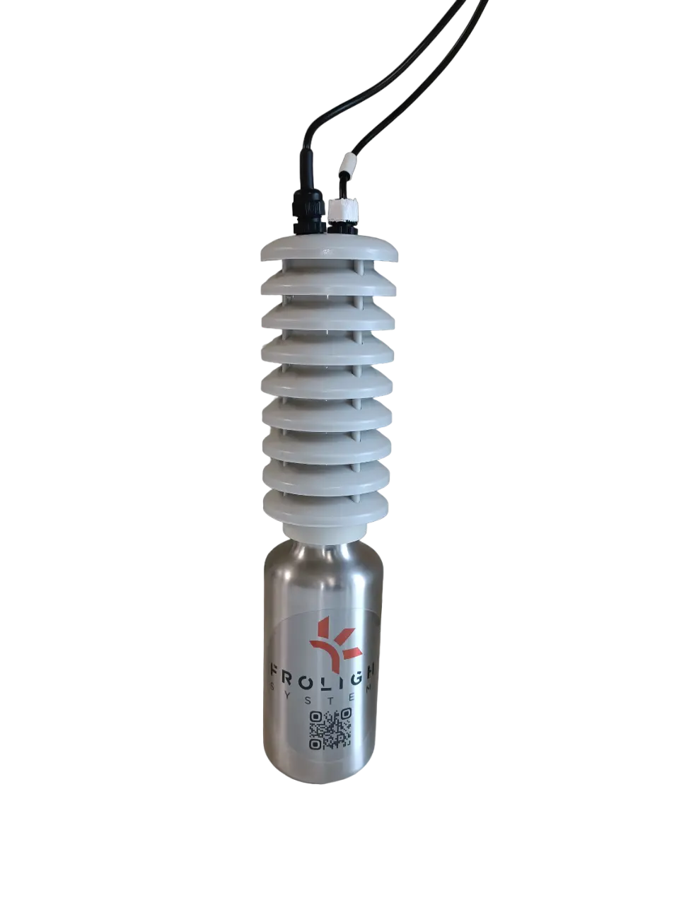
Wet Bulb Sensor (FLACTS2-M01)
A kit with a stocking and water collector is also available to make a Wet Bulb Sensor.
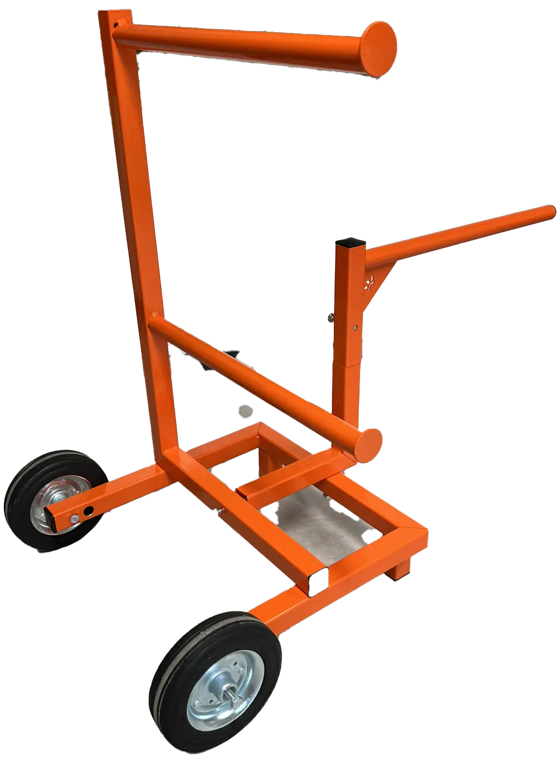
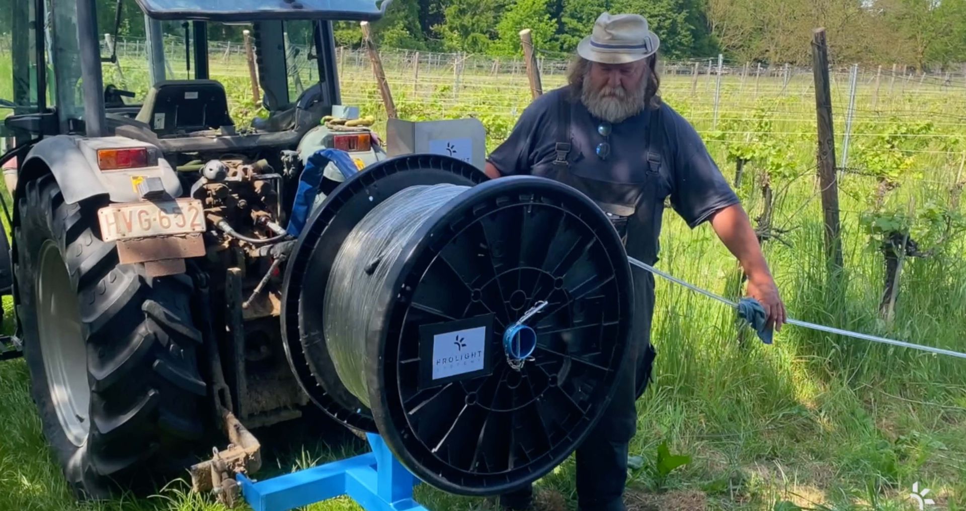
Tube Reel Trolley (FLATRA)
To ease unrolling the IR tubes, they can be placed on the tube reel trolley.
Installation
This chapter will guide you through the process of installing your Frolight system. Please read through the instructions carefully before beginning the installation process to ensure a smooth and successful setup. In this chapter, we will cover the following:
- Unpacking and verifying the components of your system
- Preparing your environment for installation
- Step-by-step instructions for installing
Before you begin, please make sure that you have all necessary tools and equipment to complete the installation. Once you have read through the instructions and prepared your environment, you can begin the installation process with confidence.
Unpacking and verifying the components of your system
Before beginning the installation process, it is important to first unpack and verify the contents of your package. This section will guide you through the process of unpacking your package, identifying the components included in your system, and verifying that you have received all the necessary components. Additionally, please verify that none of the goods were damaged during shipping. By following these instructions, you can ensure that you have Before beginning the installation process, it is important to first unpack and verify the contents of your package. This section will guide you through the process of unpacking your package, identifying the components included in your system, and verifying that you have received all the necessary components. Additionally, please verify that none of the goods were damaged during shipping. By following these instructions, you can ensure that you have
Frolight Control Units
The Frolight Master Control Unit can be identified by the serial number, which is printed on the sticker you can find on the bottom of the left side of the unit. Serial numbers like FLGCUA-XXXX.XXXX.XXXX identify Master Control Units, while serial numbers like FLGCUB-XXXX.XXXX.XXXX identify Slave Control Units.
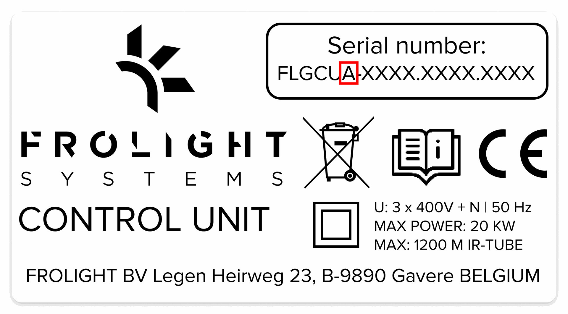
Apart from this, a plaque with a green or blue border can be found on the right side of each unit. A green border identifies Master Control Units, while a blue border identifies Slave Control Units.
Each Control Unit also comes with a coated steel mount and 5 M8x20 bolts, 5 M8 nuts and 5 A 8.4 washers.
Frolight IR-TUBES
The IR tubes are shipped on a drum. They consist out of the actual IR tube and 10 meters of electric cable with plug.
Installation Schema
Your point of sales should have provided you with an installation schema for your plot. For a successful installation, we recommend you adhere to this schema.
Preparing your enviroment for installation
We advise you to only install the Frolight system after winter pruning of the vines has happened. This will prevent damaging your system during pruning.
Step-by-step instructions for installing
This section will provide detailed instructions for installing your system. By following these step-by-step instructions, you can ensure a smooth and successful installation. In this section, we will cover the following steps:
1. Installing the Control Units
2. Installing the IR tubes
3. Connecting the IR tubes to the control units
4. Plugging in and starting the control units
Please ensure that you have read and understand all the previous sections before proceeding with the installation process. Also make sure to have all necessary tools and equipment ready, and read through each step carefully before proceeding to the next.
Warning: Make sure that the Control Units are not connected to a power source during installation. Failing to do so might damage in the system, or even result in heavy personal injury or death due to electrocution.
Required tools and equipment
- Max Tapener HT-R1 (FLAMT-HTR1)
- Max Staples (FLAMPT-ST01)
- Max Bio-Tape (FLAMT-TB01-Green)
- 6mm Allen key
- 13mm hex nut driver or hex spanner
- Protective gloves (when using a FIX-Winder)
Installing the Control Units
BEFORE INSTALLING : Always turn off or disconnect the Control Unit from the power source before installing or uninstalling.
ASSEMBLING THE MOUNT
PARTS REQUIRED: - 3x M8x20 bolt, 3x M8 nut, 3x A 8.4 washer
INSTRUCTIONS
To assemble the mount, place both feet on top of each other in a perpendicular way, so that the 3 holes align correctly. Note that the foot with the Frolight logo cut out should be the bottom foot. Next, place the large holder on top of the feet, in such a way that the holes in the bottom align with the 3 holes in the feet. To attach the holder to the feet, insert a bolt through each hole from the top, then use the Allen key and hex nut driver or hex spanner to tighten the nuts onto the bolts from the bottom. Don’t forget to place a washer between the nut and the bottom side of the feet. (See detail B)
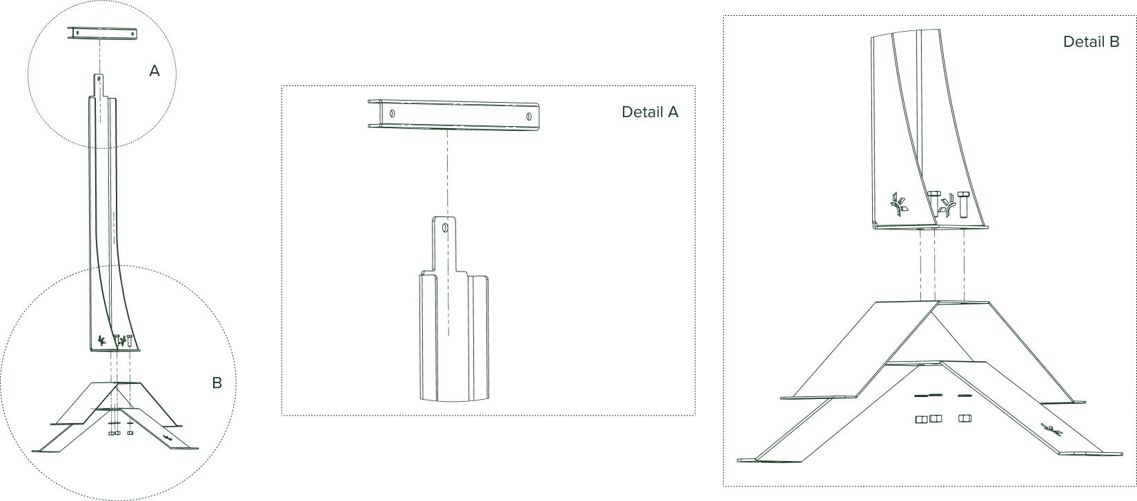
Lastly, slide the Control Unit attachment bracket over the lip (see detail A) at the top of the holder, so that the closed side points to the front of the mount (the side where the Frolight logo is visible on the feet).
You are now ready to attach the Control Unit to it’s mount.
ATTACHING THE CONTROL UNIT TO THE MOUNT
PARTS REQUIRED: - 2x M8x20 bolt, 2x M8 nut, 2x A 8.4 washer, 6mm Allen key, 13mm hex nut driver
INSTRUCTIONS
The Control Unit should be mounted to the Control Unit attachment bracket, so that the front side of the Control Unit is facing the front side of the mount (where the Frolight logo is visible on the feet of the mount).
To mount the Control Unit, open it first. Notice the 2 holes (marked below as A and B). These are the holes where the bolts should be threaded through. Insert the bolts (with washers) through the back of the attachment bracket and slide the unit over the bolts. Next, screw on a nut on each of the two bolts using the Allen key and the hex nut driver. Be careful not to overtighten the nuts to prevent damaging the Control Unit’s casing.

POSITIONING THE CONTROL UNIT
You can now position your Frolight Control Unit as defined in the installation schema provided to you by your point of sales.
Securely anchor the Control Unit to the ground by using the four holes located in the feet of the mount. Tent pegs or similar items can be inserted through these holes to keep the unit firmly in place.
CONNECTING A SECOND SENSOR TO THE CONTROL UNIT
An additional sensor can be connected to the Control Unit, assuming the sensor has a 3-pin male XLR connector. To connect the sensor, remove the cap from the unit’s 3-pin XLR chassis and securely insert the sensor’s male connector into the unit’s plug.
INSTALLING ADDITIONAL CONTROL UNITS
If your installation has more than 1 Control Unit, the above steps can be followed for installing the additional (Slave) Control Units.
Please note that a Control Unit should always be positioned at a maximum distance of 100 meter from another Control Unit. That way, the Control Units can create a so-called mesh network and communicate with each other.
Installing the IR tubes
BEFORE INSTALLING
For the Frolight IR tubes to work optimally, they should be installed in the vineyard at the level of the root stocks where the new shoots will emerge. To ensure optimal operation, place them at a distance of 3 to 10 cm from the root stock that should be protected.
When handling the IR tubes, never pull on the electrical cable part, this might damage them.
Always fully unwind IR tubes from their drums before connecting them. If you leave them coiled, this can cause serious damage and injury.
Always keep IR tubes off the ground to prevent damage and injury.
INSTALLATION STEPS
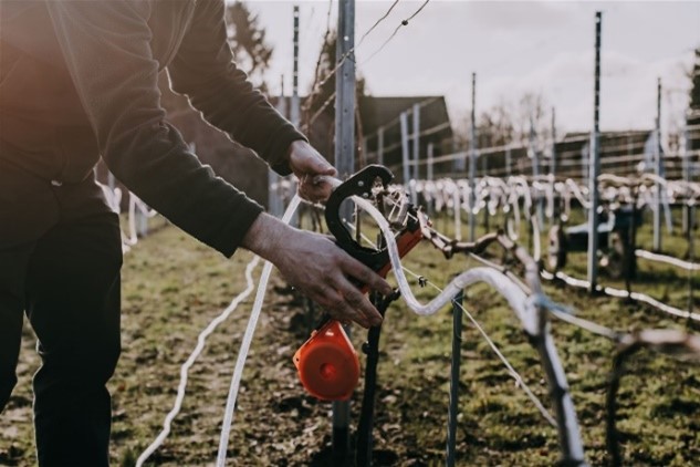
1. Unwind the reels between two rows of vines where they will be installed. Make sure to completely unwind the reels. Ensure that you start unwinding from the side which is the furthest away from the Control Unit, and move towards the Control Unit. This will ensure that the electrical cable is on the side of the Control Unit.
2. Take the IR tube in your hand and place it between 3 to 10 cm from the graft, branch or root stock to protect.
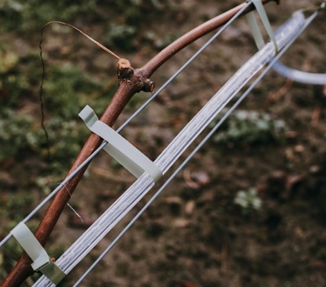
3. Fasten the IR tube using the Max Tapener HT-R1 pliers
4. Ensure that the connecting cable ends at the side of the already positioned Control Unit. You may require additional Frolight extension cables and Frolight power cable splitters (see Product overview > Parts) to reach the Control Unit.
Connecting the IR tubes to the Control Units
Now that the Control Units are positioned and the IR tubes have been installed, it is time to connect the IR tubes to the Control Units.
BEFORE CONNECTING:
Never connect more than 450m of IR tube to a group of connections (groups 1, 2 and 3).
Never connect more than 150m of IR tube to a single connection connections 1.1 – 1.4, 2.1 – 2.4, 3.1 – 3.4).
Always turn off and disconnect the Control Unit from the power source before connecting any IR tubes or extension cables.
If any part of a plug or connector is damaged, it must be replaced immediately.
CONNECTION STEPS
1. Turn off the differential fuse (DIFF) on the Control Unit.
2. Connect all IR tubes to the correct Control Unit (please refer to the installation schema provided by your point of sales). Please refer to the stickers on the box to identify the correct connection.
a) Insert the plug with the clip on the top left into the connector.
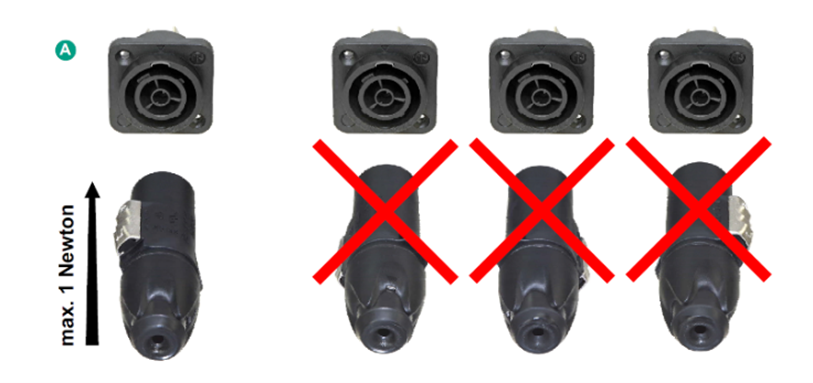
b) Lock the plug by twisting it to the right until you hear a clicking’ sound.
Connecting the Control Units to the power source
Make sure that the power supply voltage has been correctly measured by an electrician before connecting the control unit.
If a generator is used, make sure that the grounding has been properly installed and connected.
1. Connect the Control Unit to the power supply by connecting the unit’s power cable to the power source.
Note that for bigger installations, you might require more power cables & distribution boxes to connect to the power source
2. Switch on the Control Unit by switching on all fuses (F2 to F8) and the differential switch (F1). On all fuses Green means OFF qnd red means on.

After a maximum of 2 minutes, the indicator lamp will remain on and blink every 30 seconds. This indicates that the system is now operational.
When adding a (by powering) a Slave Control Unit, it will automatically connect with the Master Control Unit. A few minutes after starting up, the Slave Control Unit and it’s sensors will appear in the Control Panel.
Configuration
This chapter will guide you through the process of configuring your Frolight system. Please read through the instructions carefully before beginning the configuration process to ensure a smooth and successful setup. In this chapter, we will cover the following:
- The Control Panel
- Accessing the system’s Control Panel
- Getting acquainted with the Control Panel
- Basic configuration of your system.
Once you have read through these instruction, you can begin the configuration process with confidence.The system can be configured by accessing the Master Control Unit’s Control Panel. This Control Panel is a web interface, through which you can view and change the system’s settings and follow up on the status and performance of your system.
Accessing the system's control panel via LOCAL wifi
To access the Control Panel, you need a device (such as a smartphone, tablet or laptop) with Wi-Fi capabilities and a recent web browser (e.g. Google Chrome, Mozilla Firefox, Microsoft Edge, Safari,…) installed.
2. Open your device’s wireless network settings.
3. Connect to the Wi-Fi network named FLGCU-A-XXX (where XXX equals the last 3 digits of your Master Control Unit’s serial number).
4. Your device will prompt for a password. The Wi-Fi password to use is located in the physical manual provided with your system.
(This Manual is located inside the 'door' of the Master Control Unit, open the door with the special key.)
Once connected, open a web browser and browse to http://frolight.wlan. Please make sure to enter the exact URL (including http://) in the browser’s address bar. You should now see a the Control Panel’s Sign In screen.

6. Sign in using frolight as username and locate the password in your physical manual copy. Both are case-sensitive
You are now signed in to the Control Panel of the Master Control Unit.
Getting acquainted with the control panel
The User interface
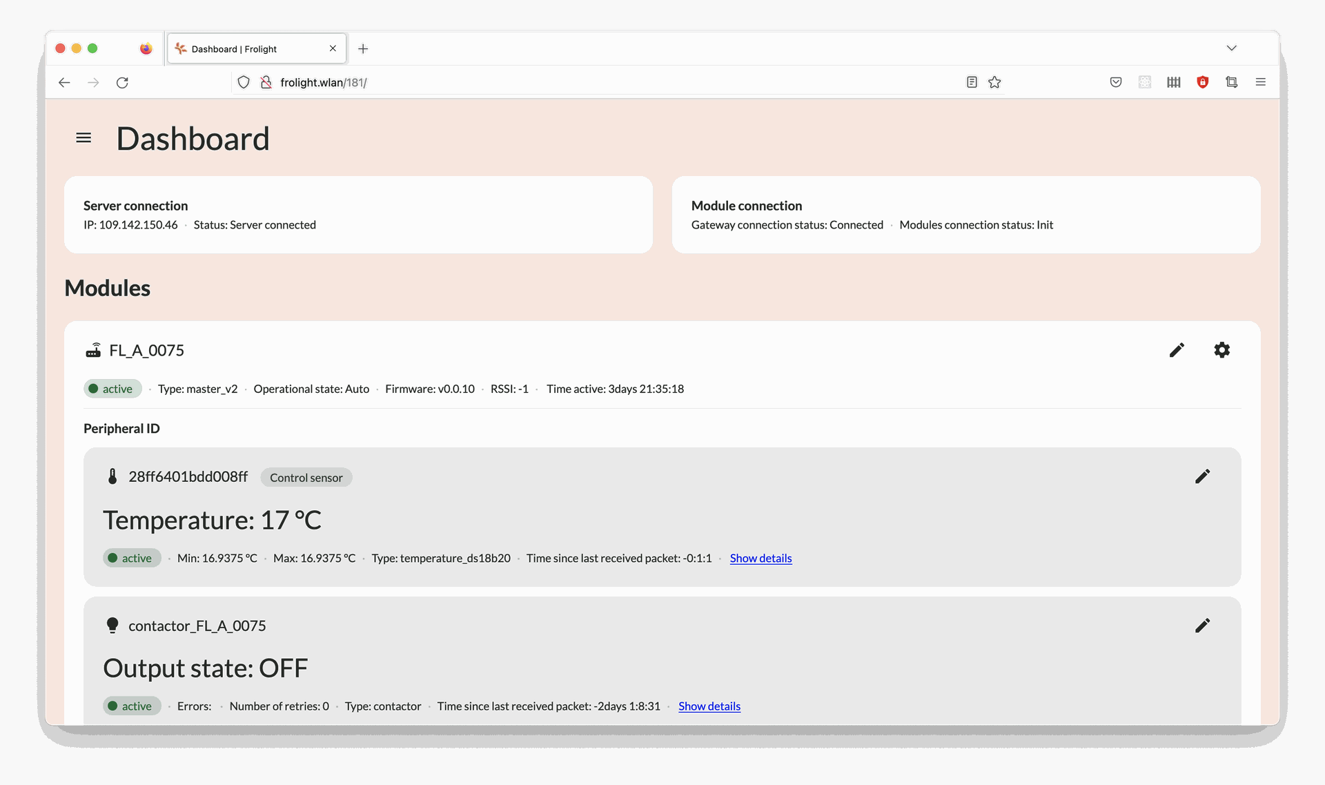
The user interface consists out of 3 primary elements:
- The current page’s title (A): This shows you which page you are currently viewing.
- The navigation button (B) & drawer (D) The navigation drawer allows you to navigate from the Dashboard page to the Settings page and vice versa. It also allows you to sign out and to change the language of the user interface.
- The page content (C) This contains the content of the current page.
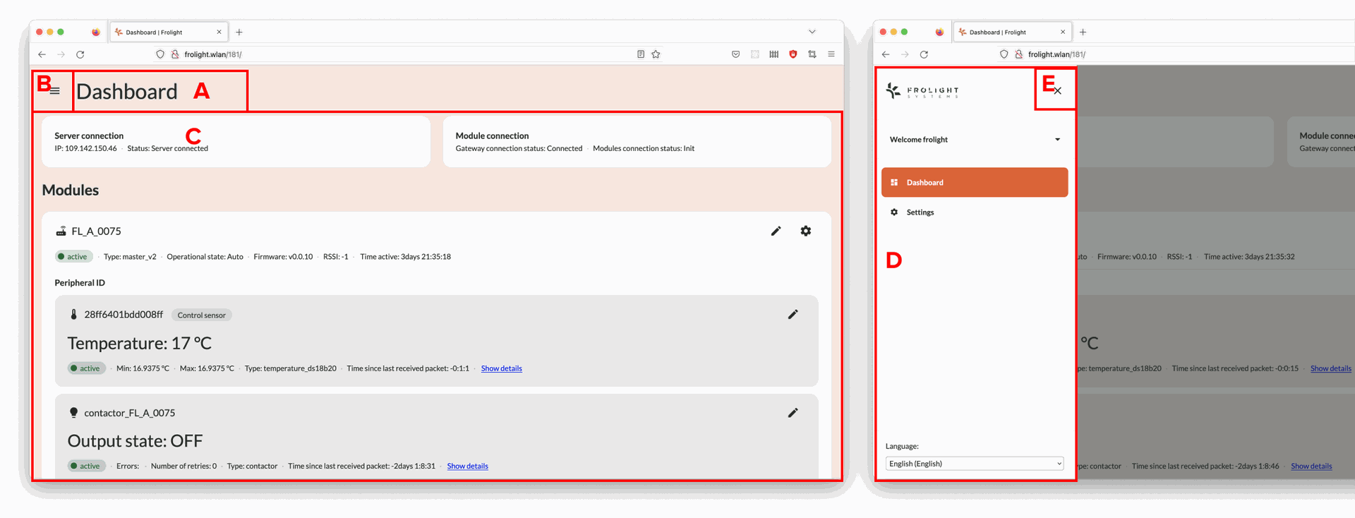
Image | © copyright Frolight BV: The User Interafce
Clicking the Navigation icon (B) in the top-left corner of the screen opens the navigation drawer (D). To close the drawer again, you can click the Close icon (E) in the top right corner of the navigation drawer.
Dashboard
The first page you see after signing in, is the Control Panel’s Dashboard page, here you can see an overview of all the Control Units, the temperature readings from their sensors and the state of the heating system (IR tubes).
Note: When the contactor’s Output state is set to OFF, the IR tubes are not active. This is because the measured temperature is above the configured threshold temperature value.
Settings
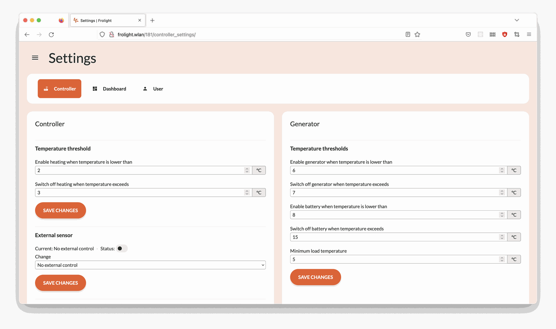
Image | © copyright Frolight BV: Settings
The Settings page has 3 tabs, shown under the current page’s title:
- Controller This tab shows all operational settings related to your Frolight installation, such as the temperature thresholds for the heating, Control Temperature Sensor selection, etc…
- Dashboard All settings related to the Dashboard page.
- User This tab contains all settings related to the user. Here you can change your password.
BASIC CONFIGURATION OF YOUR SYSTEM
The Frolight system comes pre-configured with optimal settings, but you may wish to adjust certain defaults to better suit the unique needs of your vineyard. This section highlights the essential customization options, enabling you to fine-tune the system to perfectly fit your requirements.
Temperature threshold settings
The Frolight system comes with pre-configured temperature threshold settings that automatically activate the IR tubes when the temperature drops below 2°C to provide heat to the vines, and deactivate when the temperature rises above 3°C again. However, these values can be easily customized to suit your specific needs by following these steps:
1. Access the Control Panel (see Configuration > Accessing the system’s Control Panel)
2. Navigate to the Settings page
3. Ensure you are on the Controller tab
4. In the Controller panel, locate the section labeled Temperature
threshold and adjust the values for the activation and deactivation temperatures
5. Click the Save changes button located beneath the 2 input fields
6. Confirm the changes in the dialog that appears
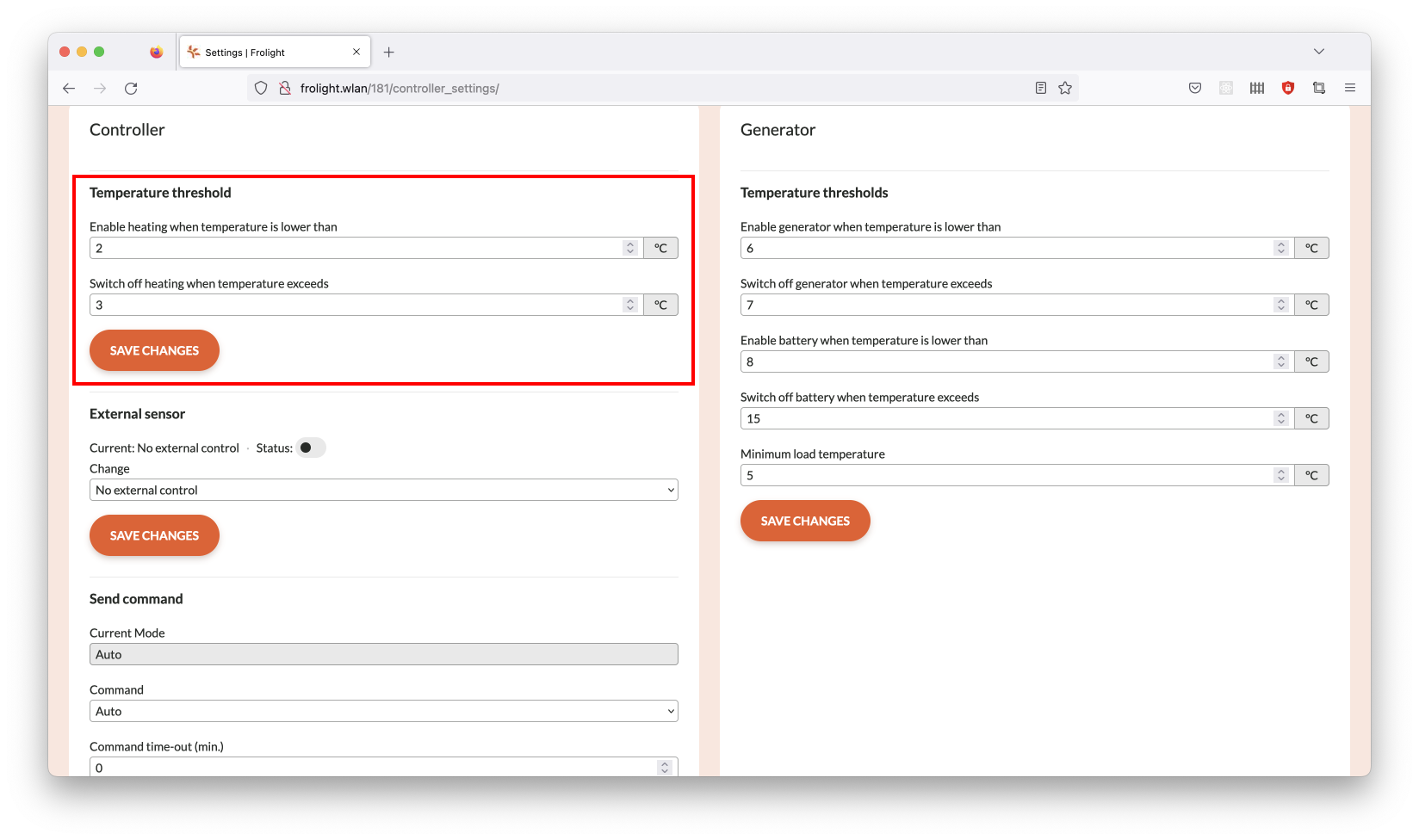
Image | © copyright Frolight BV: Temperature Treshold Settings
Please note: To prevent the system from frequently toggling the IR tubes on and off, there should be a minimum difference of 1°C between the lower and upper threshold temperatures.
Control Temperature Sensor selection
When multiple Temperature Sensors are connected to the Master Control Unit, you can specify which sensor will be used as the Control Temperature Sensor to which the heating system responds. Either the default sensor, or an external sensor. To set an external Temperature Sensor as the Control Temperature Sensor, please follow these steps:
1. Access the Control Panel (see Configuration > Accessing the system’s Control Panel)
2. Ensure you are on the Dashboard page
3. Locate the panel for the Control Unit for which you want to change the Control Temperature Sensor
4. Click the Settings icon located in the top-right corner of the panel
5. Locate the panel labeled Temperature threshold
6. Locate the field labeled Control temperature Rom ID
7. In the Change field, select the ID of the sensor you want to use as the unit’s control temperature sensor
8. Click the Save changes button located beneath this field
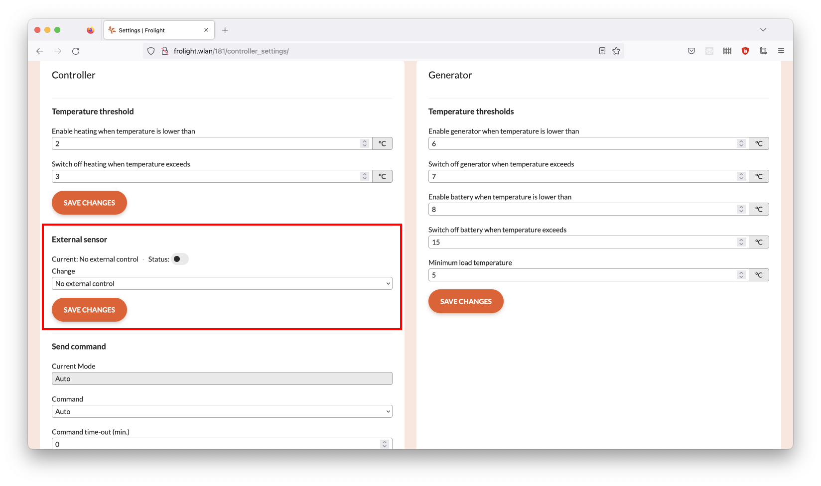
Image | © copyright Frolight BV: Control Temperature Sensor selection
Renaming a Control Unit or Sensor
If you want to change the display name of a Control Unit or Sensor, you can do
so following these steps:
1. Access the Control Panel (see Configuration > Accessing the system’s Control Panel)
2. Ensure you are on the Dashboard page
3 Locate the Control Unit or Sensor you want to rename
4. Click the Pencil icon location to the right of the display name of the Control Unit or Sensor
5. Enter the new name for the Control Unit or Sensor
6. Click the Disk icon located to the right of the input field to save your changes.
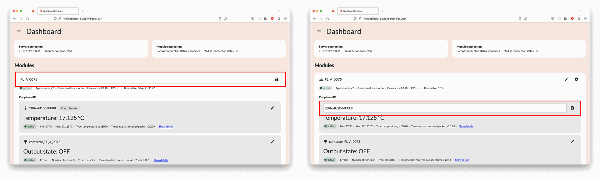
Image | © copyright Frolight BV: Renaming A Control Unit or Sensor
Operational capabilities
This chapter will provide you an overview of the various features and capabilities of the Control Panel. It is important to read through these instructions carefully to ensure you are getting the most out of your system.
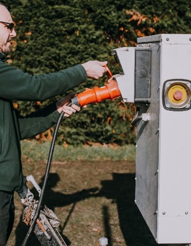
MANUALLY SWITCHING THE SYSTEM’S MODE OF OPERATION
To manually activate the IR tubes for a specific Control Unit, you can turn the hardware switch 90°. When set to Manual, the Control Unit will activate it’s connected IR tubes regardless of the temperature, until the mode is manually changed to Auto again via the hardware switch. This overrides the mode of operation you can configure via the Control Panel (see Operational capabilities > Sending a command to the Control Unit via the Control Panel).
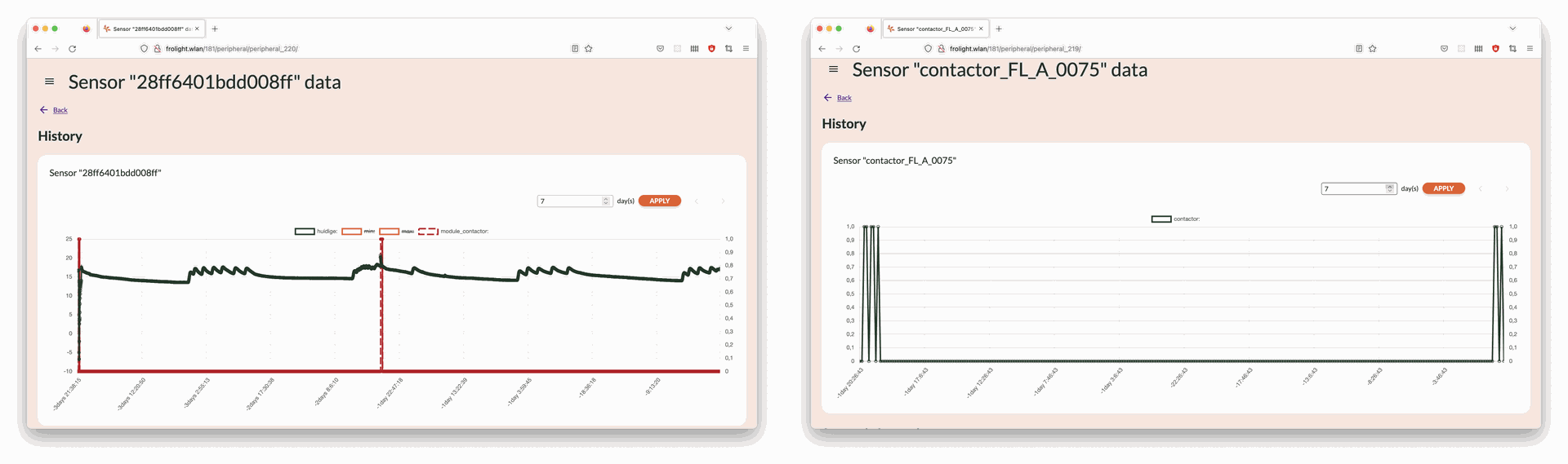
MONITORING THE SYSTEM’S DATA AND STATUS VIA THE CONTROL PANEL
The Control Panel allows you to closely monitor multiple data points, such as the currently measured temperature, heating activation status and more. To view this data in a visual format, you can follow these steps:
1. Access the Control Panel (see Configuration > Accessing the system’s Control Panel)
2. Ensure you are on the Dashboard page
3. Locate the sensor for which you would like to see the data and click the Show all link located below the
sensor’s current temperature value
4. You will now be able to see a chart visualizing the data for the past 7 days
5. To change the number of days for which the data is shown in the chart, enter a different number of days in the input field located on the top right of the chart, and then click the Apply button next to it
6. You can navigate through different time ranges by using the arrow buttons (< and >) located on the top right of the chart
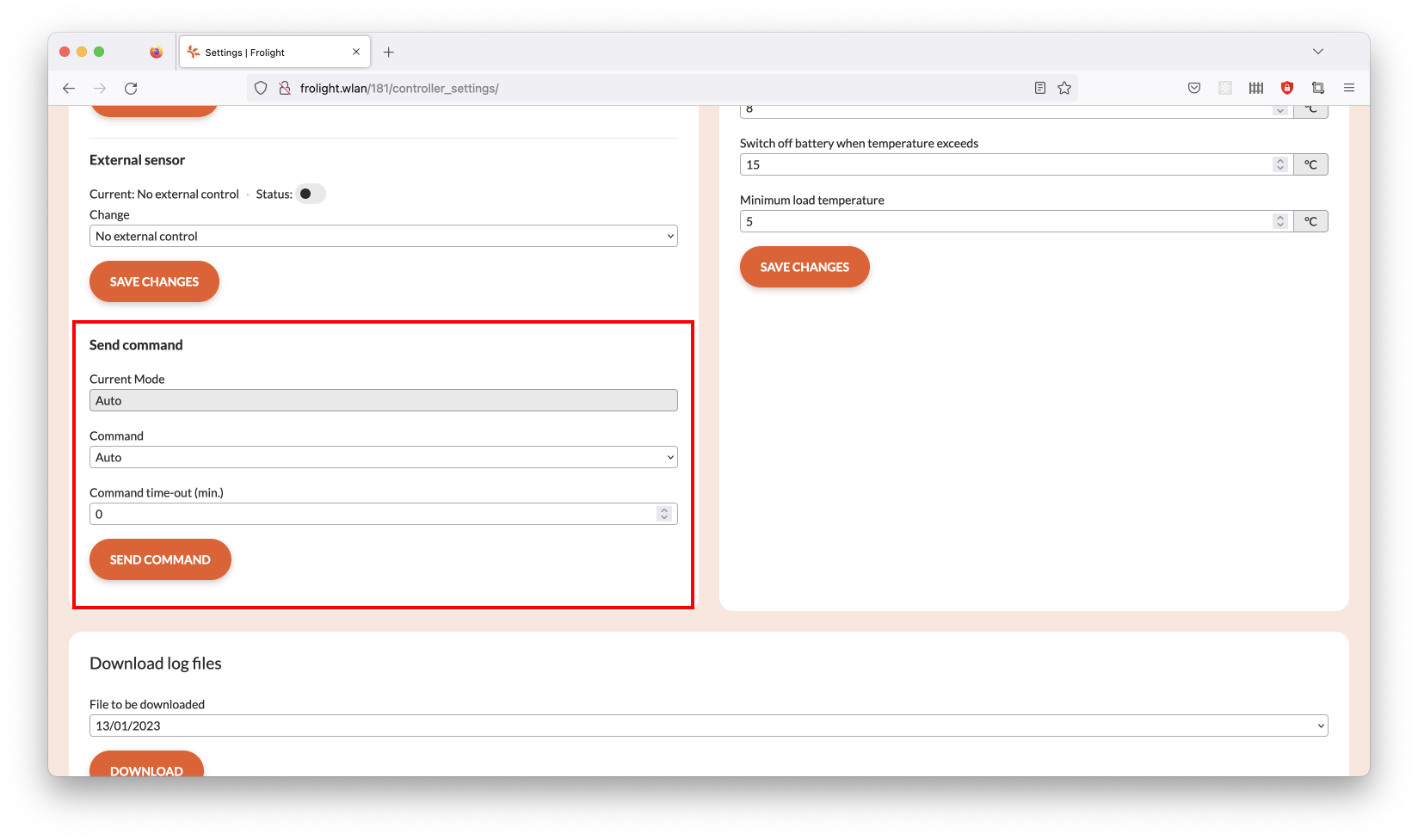
SENDING A COMMAND TO THE CONTROL UNIT VIA THE CONTROL PANEL
In certain situations, you may want to manually override the automatic operation of the system and activate the heating for a specific duration. This can be done by sending a manual command to the Control Units. To do this, follow these steps:
1. Access the Control Panel (see Configuration > Accessing the system’s Control Panel)
2. Navigate to the Settings page
3. Ensure you are on the Controller tab
4. In the Controller panel, locate the section labeled Send command
5. In the Command field, select the command you wish to send to the Control Units
a. Auto
Enables automatic operation mode (the system will decide when to turn the heating on or off)
b. Always on
This will manually activate the IR tubes for a given amount of time
6. When sending the Always on command, the value in the Command time out (Min.) field specifies the time in minutes for which the system will operate in this mode before automatically switching back to Auto mode
7. Click the Send command button located below the fields
8. Confirm the changes in the dialog that appears
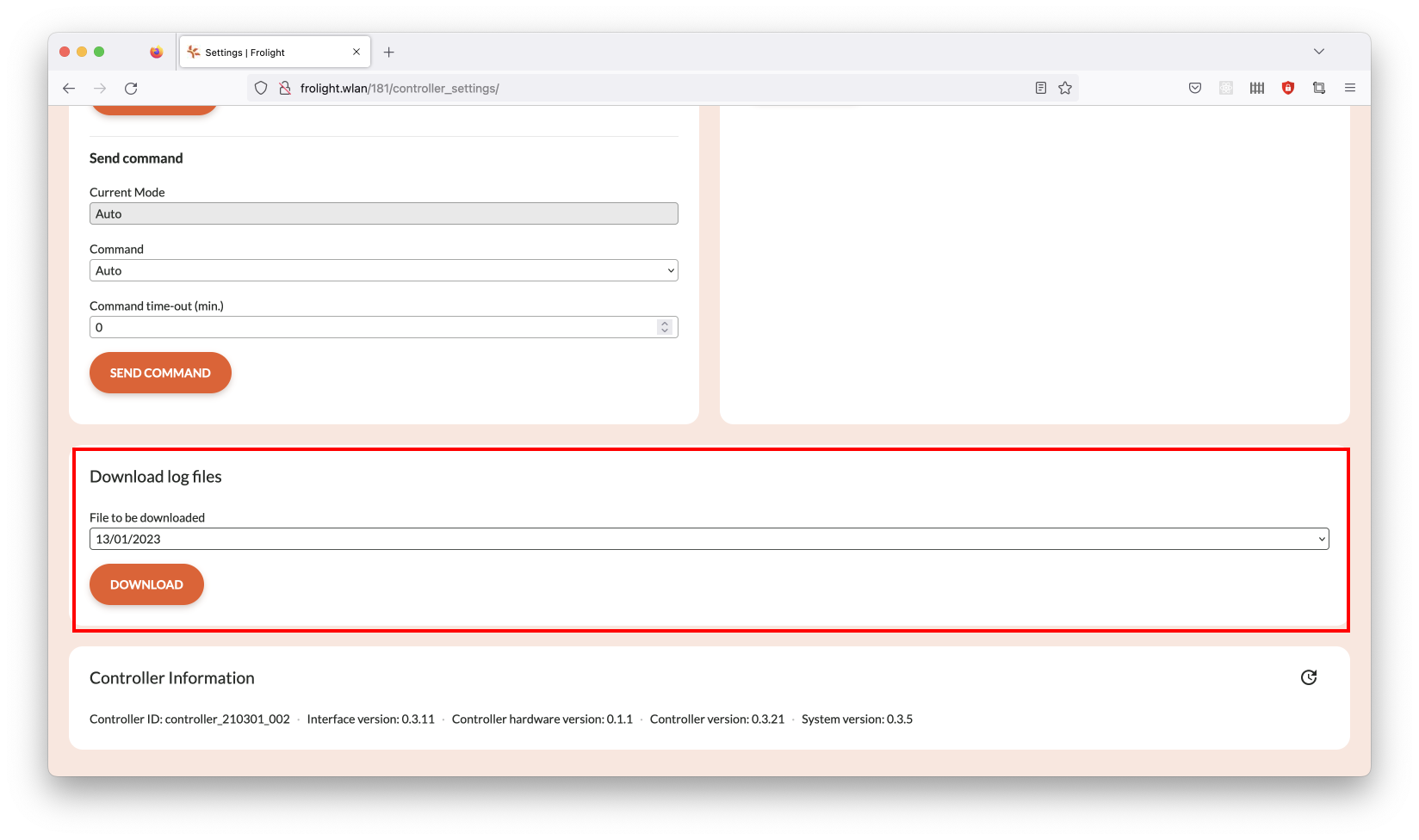
DOWNLOADING LOG FILES VIA THE CONTROL PANEL
To archive data or troubleshoot using data from the system, you may wish to
download and save a log of the data of a specific day. This can be done by
following these steps:
1. Access the Control Panel (see Configuration > Accessing the system’s Control Panel)
2. Navigate to the Settings page
3. Ensure you are on the Controller tab
4. Locate the panel labeled Download log files
5. In the File to be downloaded field, select the log file you wish to download
6. Click the Download button located below the field
MyFrolight Platform
MyFrolight is a web platform through which you can remotely monitor your installation over the internet.
The use of the MyFrolight platform is documented separately in the “Connecting a Frolight installation to MyFrolight” manual.
Maintenance and Cleaning
Regular maintenance and cleaning of the Frolight system is crucial to ensure optimal performance and longevity of the products. This chapter will provide detailed instructions on how to properly maintain and clean the various components of the system. By following these guidelines, you can ensure that your system is running at peak efficiency and reduce the risk of equipment failure. It is important to note that maintenance should be performed as needed, based on environmental conditions and usage..
Control Units
Create pages from scratch by dragging and dropping customizable building blocks. This system simplifies web design, making it accessible to all skill levels. Combine headers, images, and text sections to build cohesive layouts quickly and efficiently.
- Regularly inspect the Control Units for any damage.
- Clean the Control Units at least once per season using a clean damp cloth or sponge.
- At least once per year, before installing o please ensure all cable glands on the IR control units are sufficiently tightened.
§ 10 Nm for the large cable gland with the power cable
§ 6 Nm for the small cable gland with the temperature sensor
- please ensure all screws (inside & outside the IR control unit) are correctly tightened.
IR-Tubes
- Regularly perform a visual inspection off the IR tubes to check for cracks or tears.
- It’s also recommended to clean the IR tubes at least once per season using a clean wet cloth or sponge, preferably right before storing them.
SENSORS
- Regularly clean the Temperature Sensors with a clean damp cloth or sponge to ensure that they can provide accurate temperature readings.
Technical specifications
Control Unit
Power supply: 1 x CEE Male 32A 5p400V
Nominal Voltage 3 x 400V + N
Current max. 32A per phase
Power supply max. 20 kW
Operation modes: Manual; Temperature controlled; Other Frolight Control Unit (master/slave)
Control: Via web interface (Control Panel) Via web interface (MyFrolight platform)
Water resistance: IP65
IR tubes per control unit: max. 1200m
IR tube connection Waterproof connectors (IP67)
External connection Via cellular network (3G/4G)
IR TUBES
Available IR tube : lengths 25m, 50m, 75m, 100m, 125m, 150m
Installed power cable length: 10m
Connection: Waterproof connectors (IP67)
Troubleshooting and Support
This section will handle most common issues and their solution
Issue: No data is visible on the MyFrolight platform.
Solution: Ensure that the Master Control Unit has a operational SIM card installed, and is located in an area with sufficient cellular network reception.
Issue The IR tubes are on, even though the measured temperature is above the configured threshold value.
Solution Ensure that the hardware switch is not in the manual position, but in the automatic position. Verify via the Control Panel that the operational mode is set to Auto, and not Always on. If required, send the Auto command as described earlier in this manual.
Issue One or more sections of an IR tube do not work.
Solution The IR tubes can be repaired per meter. Contact your point of
sales for more information.
Issue When connecting a dry temperature sensor and a wet bulb temperature sensor to the Control Unit, there might be instances where the wet bulb temperature reads higher than the dry temperature, and the relative humidity exceeds 100%.
Soluition: To address this, position both temperature sensors in close proximity to minimize potential differences based on their locations. Additionally, make sure the wet bulb sensor's sleeve remains adequately moist, and the water reservoir is filled. Although minor sensor discrepancies may persist, they should not affect the overall functionality of your Frolight system.
Should you encounter any other problems with the installation or parts thereof,
please contact your point of sales as soon as possible.
Copyright Information
Frolight BV holds the copyright to this manual. All rights reserved worldwide.
This manual or parts thereof may not be reproduced, copied, translated, edited
or stored in any electronic medium without the prior written consent of the
copyright holder.
Appendices
- soon to be